Services / Plastic part design and DFM
Plastic Part Design and DFM Parts designed to come out of the mold.
Concept to production-ready CAD, by engineers who design with the mold shop's capabilities in mind. Wall sections, draft, ribs, bosses, gates and tolerances fixed where changes cost hours instead of weeks.
Reviewed by MoldMinds engineering · October 2026
- Designed against the partner shop that will actually build the tool
- DFM, material and tolerance decisions documented, not guessed
- Handoff straight into tooling, with us still on the program
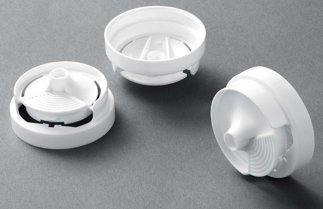
Design services from sketch to steel.
Use one piece or the whole chain.
Concept development
Rough sketches and requirements turned into viable concepts that balance function, aesthetics and manufacturability.
3D CAD engineering
SolidWorks modeling with GD&T so the part functions and the assembly fits.
Design for manufacturing
Draft, uniform wall, rib and boss design, gate placement and parting line strategy for clean, repeatable molding.
Material selection
Polymer recommendations against mechanical, chemical, aesthetic and cost requirements, with alternates.
Moldflow analysis
Simulation on the design before tooling investment, where the geometry warrants it.
Tolerance analysis
Stack-up studies so components fit the first time and warranty issues stay low.
The design decisions that decide moldability
- Nominal wall thickness. Keep walls as uniform as the function allows. Thick sections sink and slow the cycle, and abrupt transitions warp.
- Draft. Every surface that slides out of the mold needs draft, and textured surfaces need more. Check yours with our draft angle calculator.
- Ribs and bosses. Ribs add stiffness without thick walls, but a rib that is too thick at its base shows sink on the cosmetic side. Bosses need cores and support, not solid plastic.
- Radii. Sharp internal corners concentrate stress and restrict flow. Generous radii help both the part and the steel.
- Undercuts. Each one needs a slide or lifter that adds tool cost and maintenance. Many can be designed out.
- Gate and parting line. Where the plastic enters and where the mold splits decide cosmetics, weld lines and flash. They belong in the design conversation, not only the tool design.
- Tolerances. Tolerance only what the function needs. Tight callouts on every feature raise tool cost and inspection time without improving the part.
Why design and tooling should not be separate jobs
Most expensive tool changes start as design decisions made without the mold in mind. At MoldMinds the engineers who design the part also work with the shop that builds the tool, so draft, gating and steel decisions are made once, together. When the design is released it goes straight into our tooling project management without a handoff gap, and moldflow analysis is available wherever the geometry warrants it.
Sink, warp, short shots: design fix or process fix?
How to tell whether a molding defect belongs to the part design, the mold, or the process. About 90 seconds.
How a design project runs
Requirements
Function, environment, volumes, regulatory and cost targets.
Material
Resin selected for performance, environment and cost.
CAD
SolidWorks model built on DFM principles from the first feature.
DFM review
Draft, wall, ribs and gating verified against the target mold shop.
Moldflow
Fill and cooling confirmed on screen where scoped.
Tooling support
Direct support through tool design, sampling and qualification.
What you receive
- Native CAD plus STEP
- 2D drawings with GD&T
- DFM report
- Material recommendation with alternates
- Tolerance stack-up where scoped
Industries and what they demand of the design
| Medical devices | Automotive | Consumer and industrial | |
|---|---|---|---|
| Design drivers | Biocompatibility, sterilization, traceability | PPAP, durability, environmental exposure | Aesthetics, cost per part, reliability |
| Typical resins | PC, PP, medical-grade elastomers | PA, PBT, PP, ABS/PC | ABS, PP, PC, POM |
| What we document | Material certs path, validation needs | DFMEA inputs, PPAP-ready drawings | Cost drivers, secondary ops |
Part design questions, answered.
What makes your part design different?
The design is built against a specific mold shop's capability, and the same engineers stay on the program through tooling. Design and tooling decisions are made together, not thrown over a wall.
How does DFM save cost?
Draft, wall thickness, ribs and gating settled in CAD avoid tool modifications after T1, shorten cycle time, and reduce scrap. A design change costs hours; a steel change costs weeks.
What file formats do you work with?
SolidWorks native, STEP, Parasolid, IGES and most major CAD exports. Drawings as PDF or DWG.
Do you handle both simple and complex parts?
Yes, from single-cavity housings to 2K, insert and overmolded assemblies with tight tolerances.
How long does the design process take?
Depends on part complexity and how settled the requirements are. We give a written schedule after the requirements call.
Can you review a design someone else created?
Yes. A DFM review of an existing model is a common starting point. You get a written report with the changes we recommend and why, which your designer can implement, or we can.
Do you sign an NDA before reviewing a design?
Yes. Send your NDA or use our mutual NDA before you share CAD.
Bring the sketch. Leave with a moldable part.
Send what you have, from a napkin to a full CAD model. We scope the design work and quote it within one business day.
A MoldMinds engineer, not a sales team, answers every inquiry. Greensboro, NC and Mexico.